|
||||
|
The basic concepts of CNC Foam Cutting
|
||||
|
||||
|
The basic concepts of CNC Foam Cutting
|
||||
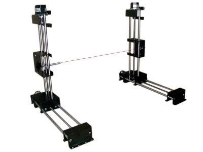
The basic concepts of CNC Foam Cutting
The idea is very simple: two carriages (left and right)
move a hot wire along a
Cutting Path.
The hot wire melts the Foam and cut it. See the photo below, where you can see
the 2 carriages and the hot wire
The concept is similar to a 3 axis CNC milling machine,
where a milling tool can cut parts, following the
Cutting Path .
What makes the process difficoult in Foam cutting is the impossibility to break
the
Cutting Path and start it again. 3 axys milling machines simply raise
the tool over the material to do that, but that is not possible here.
So the idea here is to build a single continuos
Cutting Path .
Let's make an example: we want to cut 'A' and 'B' letters. See the picture
below:
The pink shapes are the geometries of the 2 letters, and the black line is the cutting path created by devFoam. In the bottom left side you can see the Home (the starting/ending point of the travel of the hot wire). Following the arrows you can see how the external and internal contours of the letters are cut connecting the letters and making a (as little as possible) cut crossing the letters themselves.
The user can also go in edit mode, and move the entry/exit
points dragging the blue control points. See the below picture
But this is not important here, as it's an advanced
feature....
In the picture below you can see the
3D preview of the cutting job
The red lines show the real cutting path of each carriage, the green lines the
connecting lines, and in orange/cyan the cut parts
Before going on may be you want to better understand some important concepts of
devFoam. We suggest you to read well this page:
DevFoam FAQ and important concepts
