|
|
| Back to Autotracing page |
 |
|
|
|
AutoTrace - Tracing settings
|
|
AutoTrace - Tracing
settings
Pro version only
Using this dialog you can fine tuning the way the elements will be traced.
This dialog included 2 panels:
General...
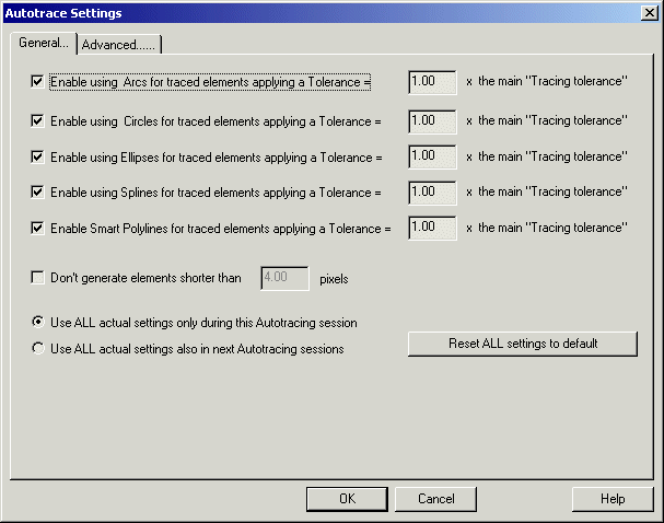
This panel includes the most used settings:

Here is the list of the parameters included there:
-
Enable using Arcs for traced elements applying a
Tolerance = Number x the main "Tracing tolerance" - When
tracing elements the process can try to use different Cad types. The most basic
one is a Polyline. But you can try to render the element as a more specific cad
element. In this case, if you enable this option, a traced element will be
rendered as an Arc, if an Arc element can fit it within a tolerance = N time
the main tolerance specified in the
Tracing elements frame. In this way you can specify a
larger tolerance for some element types, if you like to work with them then.
-
Enable using Circles....: the same as
above, but for Circle cad type.
-
Enable using Ellipses....: the same as
above, but for Ellipse cad type.
-
Enable using Spline....: the same as
above, but for Spline cad type.
-
Enable using Smart Polylines....: the
same as above, but about trying to use a Polyline with more advanced
features. For example the process will try to rebuilt good filleting of
corners, and to apply a smoother path to curves, using internally Splines and
Tangent Splines.
-
Don't generate elements shorter than Number pixels:
if enabled, only elements longer or equal to N pixels will be rendered. This is
useful to ignore dirty lines or black spots.
-
Use ALL actual settings only during this Autotracing
session : selecting this option the just modified parameters (also
those included in the next panel) will be used ONLY during this
Autotracing session. Next sessions will use the old parameters.
-
Use ALL actual settings also in next Autotracing
sessions : selecting this option the just modified parameters
(also those included in the next panel) will be used ALSO during NEXT
Autotracing session.
-
Reset ALL settings to default : ALL
parameters (also those included in the next panel) will be reset to default
values
Advanced......
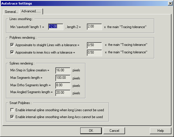
This panel includes more advanced settings, probably
you don't need modify them...

Lines smoothing
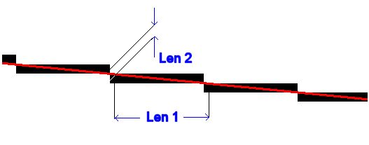
This option specify the max value acceptable to smooth 'sawtooth' pixel to a
straight cad line. The picture below shows what length 1 and length 2 are. In
Red the smoothed Cad line.

Polylines rendering
Polylines are built up often by a big number of very
small segments, may be one for pixel. Using the options specified in this frame
you can select to convert them to Lines or Arcs (Lines and Arcs of a Polyline),
according to max tolerance specified. The number here included is = N
time the main tolerance specified in the
Tracing elements frame. The larger the number, the longer the
Lines and Arcs will be, but they will fit worst the original pixels.
Splines rendering
Using Spline will help you to get smoother cad elements, but
where a long straight line is included is generally a good idea to preserve it.
With the parameters included in this frame you can limit the cases where
Splines can be applied, and how to build them can be specified:
-
Min Step in Spline creation = Number pixels
- when a spline is created, a number of control points LOWER than the number of
original pixels will be used. You can specify here the min distance
between two control points, in pixel
-
Max Segments length = Number pixels
- if the element includes a straight line longer than Number (in pixels),
a spline is not used here
-
Max Ortho Segments length = = Number pixels
- if the element includes two adiacent ortogonal segments longer than Number
(in pixels), a spline is not used here
-
Max Angled Segments length = Number pixels
- if the element includes two adiacent angled segments longer than
Number (in pixels) and creating a traingular area larger than Number x Number,
a spline is not used here
Smart Polylines
Smart Polylines method can improve the filleting and
smoothing of Polylines.
Here you can select if you want use Splines to internally smooth parts of the
polyline, and Tangent Spline to fillet corners that cannot be filleted by an
Arc.
Anyway the Spline will no be used as a Cad output type, but only for the
internal smoothing process.
See also: Step 2 -
Tracing elements
Pro version
only


