|
|
| Back to main Autotracing
page |
 |
|
|
|
AutoTrace - Step 2: Tracing elements
|
|
AutoTrace a Background image - Step 2: Tracing
elements
Pro version only
After finishing the first step (
Step 1 - Raster preprocessing), you can start the Tracing Step.
A note: we define here as Tracing the conversion of a
line/curve of black pixels in a Cad element, like a Polyline, closed Polyline,
Circle, Arc, Ellipse, Spline, Closed Spline
All the Tracing functions are included in
the second Frame of the dialog:
Lets begin with the list of the parameters and functions included there:
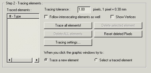
-
Traced elements list: here you can see
the list of the Traced elements, including the type of element (Polyline,
closed Polyline, Circle, Arc, Ellipse, Spline, Closed Spline). Of course the
list is empty when you start the dialog. When you select an element it will be
rendered thicker in the graphic window.
-
Tracing tolerance: this is the basic
tolerance value used during the Tracing operation. The value is in pixels, and
you can also read the size of a single pixel. In the
Tracing settings dialog you can then set some tolerance factor
for some special cases.
-
Follow intersecating elements as well. If
this option is enabled, when you click an element in the raster image will be
traced not only it, but also all the intersecating elements. In this way you
can Trace a group of connected elements (lines, curves) in a faster way.
-
Show Vertices. If this option is enabled
you can see also the vertices of the Traced elements, rendered with a little
Green square.
-
Trace all elements! Pressing this button
ALL the elements included in the raster (or in the selected zone) will be
traced. This is the fastest way to go if you want to trace all what you can see
-
Delete selected element. Pressing this
button the element selected in the Traced element list will be deleted
-
Delete ALL elements. Pressing this button
ALL the elements included in the Traced element list will be deleted. If you
want Trace again elements rememeber to click the 'Reset deleted Pixels' button
before!
-
Reset deleted Pixels. A brief
introduction: when you trace an element all the pixels crossed by that element
are marked as deleted. This is to avoid to trace more times the same elements.
In the combo box included in the
Raster preprocessing frame you can select if you want to see on the
screen also the marked as deleted pixels or not. If you need to trace
again some elements, you need to unmark the pixels: this is what this
button does.
-
Tracing settings: goes to the
Tracing settings dialog, where you can fine tune the way the elements
are traced.
-
When you click the graphic windows try to
:
-
Trace a new element - clicking a black
line/curve in the graphic window it will be traced (manual Tracing)
-
Select a traced element - clicking a red
traced element it will be selected in the Traced elements list.
You can adjust the transparency of the raster image
scrolling the included cursor.
Now the content of the frame is explained, but lets add some more information.
You can Trace elements in two ways:
-
Automatic tracing: simply press the
Trace
all elements! button and ALL the elements included in the raster
(or in the selected zone) will be traced. You can then delete some unwanted
elements here or after in the Cad Drawing window. You can also setup a minimal
length for the elements to trace, see
Tracing settings dialog.
-
Manual tracing: click some black
line/curve in the graphic window (with Trace a new element mode
enabled!) and it will be traced. If the Follow intersecating elements as
well option is enabled, also the intersected line/curves will
be recursively traced. This can speed up a lot the Tracing of a group of
connected elements.
I repeat here an important concept: when you trace an
element all the pixel crossed by that element are marked as deleted. This is to
avoid to trace more times the same elements. In the combo box included in the
Raster preprocessing frame you can select if you want see on the screen
also the marked as deleted pixels or not. If you need to trace again some
elements, you need to unmark the pixels, using the Reset deleted Pixels.
button.
The traced elements are rendered in Red in the graphic window. The selected one
is thicker. You can see the vertices of the Traced elements enabling the Show
Vertices option.
When the Tracing job is finished press the OK button, and
all of them will be added to the Cad Drawing
See also Autotracing
for a step by step example
Pro version
only