|
||||
|
Stl part - Customize Rotations
|
||||
|
||||
|
Stl part - Customize Rotations
|
||||
Stl part - Customize Rotations
You can get this dialog box pressing the 'Customize Rotations' button located in the 'Cut Stl Part' page.
Using this feature You can then create
manually or in automatic way a number of NOT equispaced rotations, to cut the
part in a faster and better way than the strandard old way.
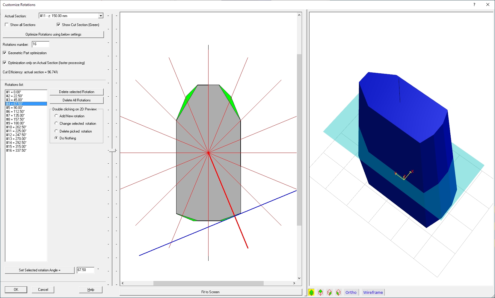
For example You can can see here below the Blue part cut by 16 standard
equspaced rotations.
The central 2D picture shows a selected section along the Part Z height.
The Gray Region shows the section of the STL part, the Green
Regions show the material that cannot be cut using these
rotations.
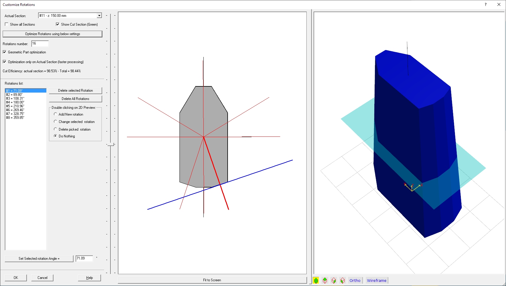
In the below image you can see the result after we pressed
the 'Optimize Rotations using below settings' button.
We asked for 16 rotations, but the Smart part of the application created just 8
rotation, and each rotation as you can see is optimized according
to the original STL part geometry.
In this way the cut will require Half the time, and the result won't require
further sanding!
Now we will explain in deep every single part of the dialog.
Left side: the parameters and commands
Actual section: You can select here (or
moving the Vertical cursor placed just before the 2D preview) the actual XY
section.
Show all sections: Enabling this option also the other section
will be rendered as light gray in the 2D Picture.
Show Cut section (Green): Enabling this option the part
of uncut material (after the cut is applied) will be rendered as Green. The
better the rotations settings, the lower the Green Area.
Optimize Rotations using below settings: Pressing this button the application will automatically generate a set of Optimized rotation. You can specify the Max number of rotations (the application is free to apply a lower number, is no more rotaions are required).
Geometric Part optimization: Enabling this option the STL part will be processed as a Geometric part (when the eye can see a limited number of faces...). If not the STL part will be processed as an Artistic part, where usually a big number of faces are included. You can try both methods, then apply the one gives a larger Cut Efficiency value and smaller Green Regions.
Optimization only on Actual Section
(faster processing): Enabling this option the STL part will be
processed faster, considering only the Actual section. If not, all the sections
will be processed, and the result can be better.
Manual rotation management:
You can also manage manually the Rotations, may be because
some side of the final part is more important for you.
In this case you must refer to the Rotation list, where all the rotations
are listed.
Note: The rotations will be the same for all Section.
You can start for example by deleting All rotations, using the 'Delete All
Rotations' button.
Then in the 'Double clicking on 2D Preview:' frame you will select 'Add New
Rotation' as action.
At this point move the mouse in the 2D preview, you can see a Black line
that indicates the rotation angle, and a perpendicular Blue line indicating the
HotWire. Just move the mouse to have the Blue line parallel at the segment you
want to cut during that rotation, and double click the left mouse button. A new
rotation will be added to the List.
Note: it is not important to place the blue line near or over
the segment you want to cut, just consider to see them parallel, as you are
setting here just an angle!
You can now:
- Add new rotations doing the same for another segment
- Modify the rotation selected in the list enabling 'Change
selected rotation' action and double clicking on the new rotation place in the
2D Preview
- Delete a rotation using the 'Delete selected
Rotation' button, or enabling 'Delete picked rotation' action and double
clicking on the rotation you want to delete
- if you want apply an accurate value to a rotation, just select it in the
list, set the right angle after the 'Set Selected rotation Angle = ' button,
and press that button.
Middle side: the 2D preview
I think the better thing is to explain what you can see here by colour and type.
Pressing the 'Fit to screen' button you will maximize the drawing to the 2D preview window size.
Right side: the 3D preview
You can see here the 3D Preview of the Stl part.
You can also see a transparent Cyan rectangle indicating the actual XY section.
The optional grid can be customized by the '3D Preview' menu.
You can make measurements on the 3D preview selecting the Orthogonal view and
some predefined Top-Side-Front view.
Pressing OK you will go back to the 'Cut
Stl Part' page, with the new rotations setting.
Pressing Cancel you will go back to the 'Cut
Stl Part' page, with the old rotations setting.
