|
||||
|
Stl part
|
||||
|
||||
|
Stl part
|
||||
Stl part
You can get this dialog box pressing the 'Cut Stl part' link located in the Startup dialog
You can use this if you own a Cnc machine with an added rotary axis. If you press ' Cut Stl Part' link the following dialog will appear:
A Stl part is a solid described by a triangular meshed
surface, supplied by an external Stl file.
The Stl file must follow the rules of the Stl standard, or some problem can
arise. The application check the most important rules and show a warning is
some problem happened.
Stl files are well known, as this is the standard file format used by 3D
Printers.
You can generate and modify Stl files using the supplied devStl Tool
application, you can run it from the Startup dialog.
For some regular shape may be you will find more convenient to use a
'TwistRot Part', the cut in this case will be more accurate and faster.
The cut will be performed dividing the part in projected section, one for each
rotation.
A projected section is the contour of the shadow of the part on a
plan, created by a Collimated light (a Collimated light is light
whose rays are parallel).
Then, for each rotation, the hotwire will follow the right side of this path.
After every cut, the hot wire goes to the safe position (optional), the foam
block is rotated, and a new cut applied.
Of course the hotwire cannot render well concavities along its length. So, if
the part includes concavities, we suggest to select well the Rotation axis, to
minimize them.
If internal holes are created in the Path, they will be ignored. So, again,
take your time to evaluate the best Rotation axis.
If possible try to avoid also up/down movements changes during every single
cut, this can affect the quality of the final part.
To load a new Stl file use the 'File - Import a Stl
file' menu, see below the full description of the menu.
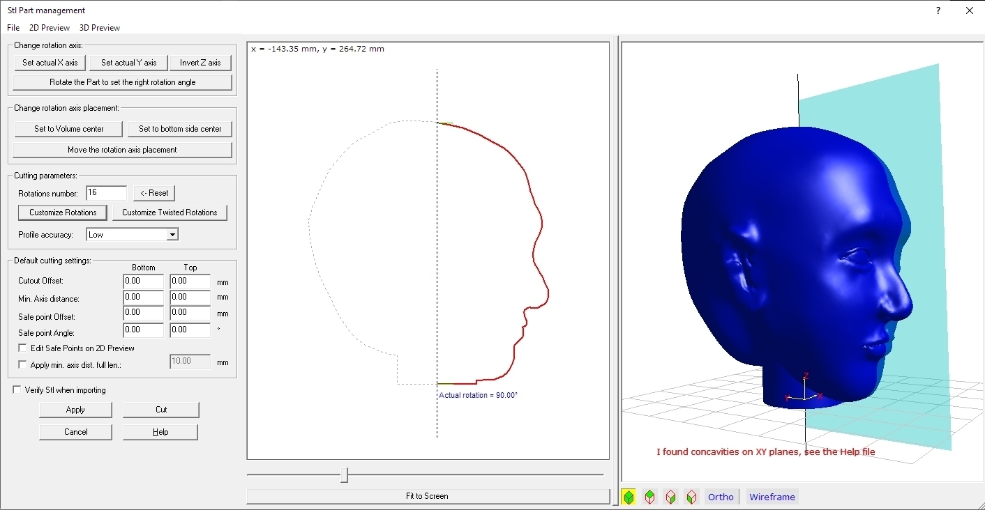
In the left side of the dialog you can see the controls to setup your Stl part.
In the middle a 2D preview, showing the computed projected section for the
rotation selected by the horizontal cursor.
In the right side the 3D preview of the Stl part.
Now we will explain in deep every single part of the dialog.
Left side: the parameters and commands
Change rotation axis Frame:
When you import a new Stl file, the original Z axis
is used as the rotation axis.
You can here select a new rotation axis between X and Y, considering that the
applied rotation axis will be the Z axis, as shown in the 3D picture.
You can also select to invert the orientation of the Z axis, if you want a
Top/Down inverted cut.
If this is not enough, as you have a Part with a strange angle, press the 'Rotate
the Part to set the right rotation angle' button. You will see
in the screen this new window:
You can as first select the axis to use to perform the rotation, and the right
View will be displayed in the 3D picture.
Then just press on of the button surrounding the angle step to apply some
rotation. Every button will apply a 1 x angle step, 5 x angle step, 15 x
angle step.
You can also select to use the Orthogonal view this can help to have a better
control over the 3D picture.
Then just press OK to confirm the new settings, or Cancel to ignore them.
Change rotation axis placement Frame:
When you import a new Stl file, the Z will be centered on the
Volume Center of the part, considering its max/min X and Y coordinates.
If you need to make more adjustements, just press the 'Move the rotation
axis placement' button. You will see in the screen this new
window:
You can as first select the axis to use to perform the movement, and the right
View will be displayed in the 3D picture.
Then just press on of the button surrounding the distance step to apply
some rotation. Every button will apply a 1 x distance step, 5
x distance step, 15 x distance step.
You can also select to use the Orthogonal view this can help to have a better
control over the 3D picture.
Then just press OK to confirm the new settings, or Cancel to ignore them.
Cutting parameters:
You select here:
Default cutting settings Frame:
Here you can apply important refinements to the cut:
Verify Stl when importing: checking this option, when you import a STL file it will be verified. If the application finds some problem you will advised, so you have the possiblity to fix them. You can for example use DevStl Tools to fix them, see the Startup dialog to run it. Enabling this option will perform longer processing time during the import job.
Command Buttons:
Middle side: the 2D preview
I think the better thing is to explain what you can see here by colour and line type. Consider also that you can turn on-off some components by the '2D Preview' menu.
Pressing the 'Fit to screen' button you will maximize the drawing to the 2D preview window size.
Right side: the 3D preview
You can see here the 3D Preview of the Stl part. Consider also that you
can customize it by the '3D Preview' menu.
The transparent cyan plan can be rotated by the horizontal slider
placed at the bottom side of the 2D preview. This define the plan where
the shadow will be projected, just imagine the plan all behind the part, to
receive the full shadow.
Here is displayed attached to the Rotation axis, as we think is more intuitive.
The optional grid can be customized by the '3D Preview' menu.
You can make measurements on the 3D preview selecting the Orthogonal view and
some predefined Top-Side-Front view.
The menu
Using the supplied menu you can control all the advanced settings.
File menu:
2D Preview menu:
3D Preview menu:
I suggest also to take a look at this page, to better understand some important concepts of devFoam: DevFoam FAQ and important concepts
