|
||||
|
Lathe type Milling finishing
|
||||
|
||||
|
Lathe type Milling finishing
|
||||
Lathe type Milling finishing (devFoam 3DM 2 only)
You can get this dialog box pressing the 'Lathe type milling finishing' button located in the Startup dialog or by the Mill menu item of 'Stacked parts' dialog.
You can use this if you own a
Cnc machine with an added rotary axis and 3 linear axes for Lathe
type milling.
This milling job is usually used as a finishing job for sculpted parts, after
you used a Lathe type cut to rough the foam.
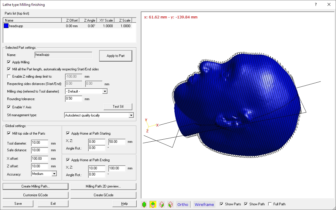
The following dialog will appear if you select a Stl part:
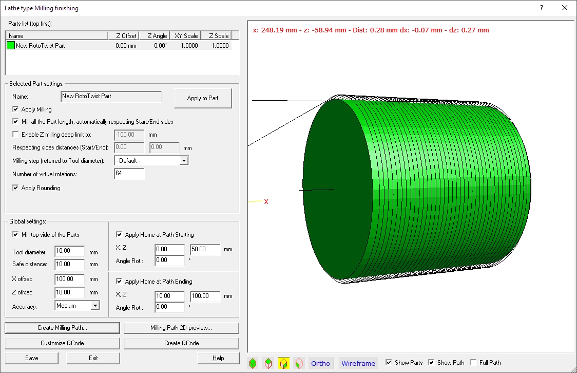
Or this if you select a TwistRot part:
In the left upper side you can see the list of the stacked
parts you are going to mill.
Select one of them (it can be a Stl or a TwistRot part) and go to customize its
settings, see below.
As you can see the settings slightly changes selecting a Stl or a TwistRot
part.
a) caseStl Part settings:
This frame includes the settings to specify the way you want
to mill the Stl part.
Apply milling - you can select if you want to mill or not this
part, this has a sense when you have multiple stacked parts.
Mill all the Part length, automatically respecting Start/End sides
- you can specify if you want to mill the full length of the part, or you want
to respect some start/end sides.
Unselecting this option will enable the possibility to insert the length of the
Start/End sides, just below.
Enable Z milling deep limit to: value - you can limit
here the Z height of the milling tool to the specified value.
Milling step (referred to Tool diameter): - you can set here
the length of the milling step (the step of the milling tool along the X
axes after every turn of the rotating axes. This is defined as a fraction of
the milling tool diameter.
A lower value will get better finishing, but a longer working time.
Rounding tolerance: value = A lower value will get
better finishing, but a longer working time.
Enable Y Axis - you must disable this option if your Cnc
machine just performs 2 linear milling axes. With 3 axes the quality of the
final result will be better, as the milling tool can then reach deeper sides.
Test Stl - Test if the Stl has internal
problems
Stl management type: - you can specify here if you have a bad
or good quality Stl file. Or just let the application select the best
approach... A Good Stl file (Test Stl = OK) can be processed faster if Good Stl
is selected. If you have doubt just go with the Automatic setting.
Apply to Part - pressing this button will apply the new
settings to the Stl part, you can then use the 'Create Milling Path...'
button to see the results in the 3D preview
b) caseTwistRot Part settings:
This frame includes the settings to specify the way you want
to mill the TwistRot part.
Apply milling - you can select if you want to mill or not this
part, this has a sense when you have multiple stacked parts
Mill all the Part length, automatically respecting Start/End sides
- you can specify if you want to mill the full length of the part, or you want
to respect some start/end sides. Unselecting this option
will enable the possibility to insert the length of the Start/End sides, just
below.
Enable Z milling deep limit to: value - you can limit
here the Z height of the milling tool to the specified value.
Milling step (referred to Tool diameter): - you can set here
the length of the milling step (the step of the milling tool along the X
axes after every turn of the rotating axes. This is defined as a fraction of
the milling tool diameter.
A lower value will get better finishing, but a longer working time.
Enable Y Axis - you must disable this option if your Cnc
machine just performs 2 linear milling axes. With 3 axes the quality of the
final result will be better, as the milling tool can then reach deeper sides.
Number of virtual rotations: value - the idea
here is that to get for example a cylinder, you can just cut it with a small
number of cutting step (to rought it), then you can specify here a larger
number and the final result will be much better
Apply rounding - if enabled we suppose
you want to get a rounded surface for the part, and the milling job if
performed removing the corners. Use it with a high value of Number of
virtual rotations to have a smooth rounded surface
Apply to Part - pressing this button will apply the new
settings to the Stl part, you can then use the 'Create Milling Path...'
button to see the results in the 3D preview
Global settings:
This frame includes the global settings of the Job. Also
these settings will be saved in a simple Stacked part file if you the press the
'Save' button, so you can reuse it, but this are more general settings, less
related to your Stl
Part, but more to your Cnc machine and way to work. Some of these parameters
won't require a full Path creation. The settings requiring that will
be followed by an asterisk: (*).
Mill from the top side of the Part - checking this option the
job will start from the top side of the original Stl part, in the other case
from the bottom side.
Tool diameter: value - the diameter of the milling
tool (*)
Safe distance: value - the safe distance of the
milling tool from the part, during fast movements.
X offset: value - an offset value added to the X axes
Z offset: value - an offset value added to
the Z axes
Accuracy: - the required accuracy of the milling job. A higher
accuracy will perform an higher part quality, but with a slower computing time.
(*)
Apply Home at Path Starting - you can select here if you want
top apply a starting Home position, you must then define all the required value
for the axes.
Apply Home at Path Ending - you can select here if you want
top apply an ending Home position, you must then define all the required value
for the axes.
Command buttons:
Create Milling Path.... - Create the milling
path and update the 3D preview
Milling Path 2D preview... - run the
'Milling preview by single section' dialog where you can check for
every section the way the milling tool will move.
Customize GCode - Start the
'G-code file creation settings for Stacked Parts foam Milling' dialog,
where you can customize the GCode
Right side: the 3D preview
You can see here the 3D Preview of the part, including
the milling path.
You can make measurements on the 3D preview selecting the Orthogonal view and
some predefined Top-Side-Front view.
Show parts - Show the parts in the 3D
Preview
Show Path - Show the milling path in the 3D Preview
Full Path - Show also the path behind the Parts in the 3D
Preview
