|
|
| Back to Wizard page. |
 |
|
|
|
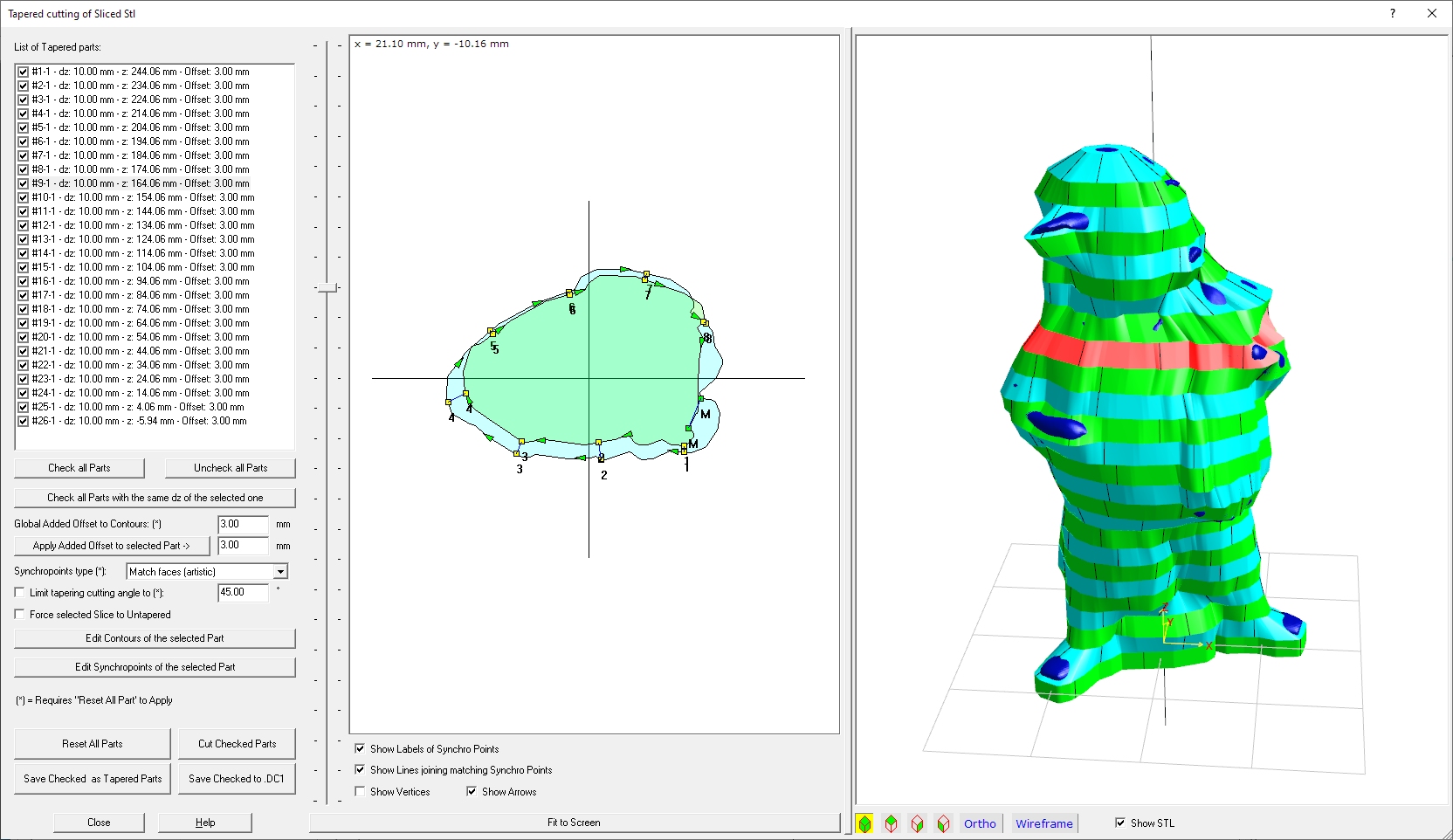
Stl part: Tapered cutting of Sliced Stl
|
|
Stl part: Tapered cutting of Sliced Stl
You can get this dialog box pressing the
'Cut as Tapered Slices' link located in the 'Cut
Sliced Stl Part'
You can use this if you just
own a Cnc machine with 2 or 4 linear axes. If
you press 'Cut as Tapered Slices'
button the following dialog will appear:
Using tapered parts will create a better result and less
sanding will be required. But you need here 4 linear independent axes and the
cutting process can be longer and more complex.
Now we will explain in deep every single part of the dialog.
Left side: the parameters and commands
List of Sliced Parts:
You can see listed here all the Sliced part defined in the
previous dialog.
For each item you can see the dz value (the thickness of the foam panel you'll
use then), the z height where the Slice is placed and the optional Offset.
You can also switch off parts Unchecking them.
When you go then to export/cut them, you can also select all the Slices with
the same thickness of the selected one just by pressing the 'Check all Parts
with the same dz of the selected one' button.
Other parameters and
buttons:
-
Section interpolation type: every slice
can be internally computed splitting in in sub-slices, and using then the Union
of all the XY sections as shape of the final Sliced part.
You can select among None/Light/Medium/Best where None doesn't apply
subinterpolation and Best uses the more accurate interpolation.
This parameter can help you when some slice have internal sections larger than
the upper/lower section, to avoid to cut a too little sliced part.
-
Global Added Offset to Contours: (*) value:
you can apply here a Global (valid for all Sliced parts) offest value. This
offset value will increase the size of the Sliced parts, to have more material
for the sanding job.
-
Apply Added Offset to selected Part -> value:
this is similar to the above option, but this value can be customized
for each single Sliced part.
-
Synchropoints type (*): Sinchropoints are
referrence points used to create the tapered part. The hotwire will then reach
every synchropoints couple at the same time. These the type of precomputed
synchropoints you can apply:
-
None: in this case no synchropints will be generated.
-
Smart: the application will evaluate for a good enough type
-
Match sharp points (geometric): use this setup if you want
to use Sharp corners as synchropoints. This is usyually good for geomertic
type STL
-
Match faces (artistic): use this setup for artistisc type
stl, like sculpted objects, for example
After selecting a different type Press the 'Reset All Parts'
button to apply them.
You can then modify/refine the Synchropoints using the 'Edit Synchropoints
of the selected Part' button
-
Limit tapering cutting angle to (*): angle
value: Cnc hotwire machines don't like a very big angle on the hotwire
(big difference on left/right carriages paths). Using this parameter you can
automatically limit the max angle, by increasing the smallest up/down section
-
Force selected Slice to Untapered: some
Sliced section can be problematic cause too different up/down sections. In this
case you can force that section to be created as a untapered part.
-
Edit Contours of the selected Part: using
this button you can go to graphically modify the contours of the selected
Sliced part
-
-
Reset All Parts: pressing this button all
the tapered parts will be recreated using the selected above parameters marked
with (*)
-
-
Save Checked as Tapered Parts: you will be
prompted for a Folder and a Prefix Name for the Tapered files that will be then
created
-
Save Checked to .DC1: you will be
prompted for a .DC1 file name where the selceted section contours will be included
Middle side: the 2D preview
In the 2D preview you will see the geometry of the
actual Tapered part as an upper and lower XY sections.
You can navigate the sections by selecting a different item in the Sliced
parts list, or just moving the vertical cursor placed at the left side of
the 2D preview.
You can select to Show the added lines and elements using the Check boxes
placed below the 2D preview
Pressing the 'Fit to screen' button you will maximize the
drawing to the 2D preview window size.
Right side: the 3D preview
You can see here the 3D Preview of the Stl part (optional)
and all the checked Sliced parts
The actual Sliced part will be rendered as Red.
If you have the STL part enabled and you see some part of it out of the Sliced
part, you can increase the Added Offset value
.