|
||||
|
Stl part: sliced cutting
|
||||
|
||||
|
Stl part: sliced cutting
|
||||
Stl part: Sliced cutting
You can get this dialog box pressing the 'Cut Sliced Stl part' link located in the Startup dialog
You can use this if you just own a Cnc machine with 2 or 4 linear axes. If you press ' Cut Sliced Stl Part' link the following dialog will appear:
A Stl part is a solid described by a triangular meshed
surface, supplied by an external Stl file.
The Stl file must follow the rules of the Stl standard, or some problem can
arise. The application check the most important rules and show a warning is
some problem happened.
Stl files are well known, as this is the standard file format used by 3D
Printers.
You can generate and modify Stl files using the supplied devStl Tool
application, you can run it from the Startup dialog.
For some regular shape may be you will find more convenient to use a
'TwistRot Part', the cut in this case will be more accurate and faster.
This approach is different than using the
'Cut Stl Part' command.
Sliced cut split the orginal STL part in a number of Slices, then you can cut
them as tapered or untapered parts (see
below) using a simple hot wire machine with no rotary axis.
Using this approach you can also cut internal holes or concavities in the XY
sections.
To load a new Stl file use the 'File - Import a Stl
file' menu, see below the full description of the menu.
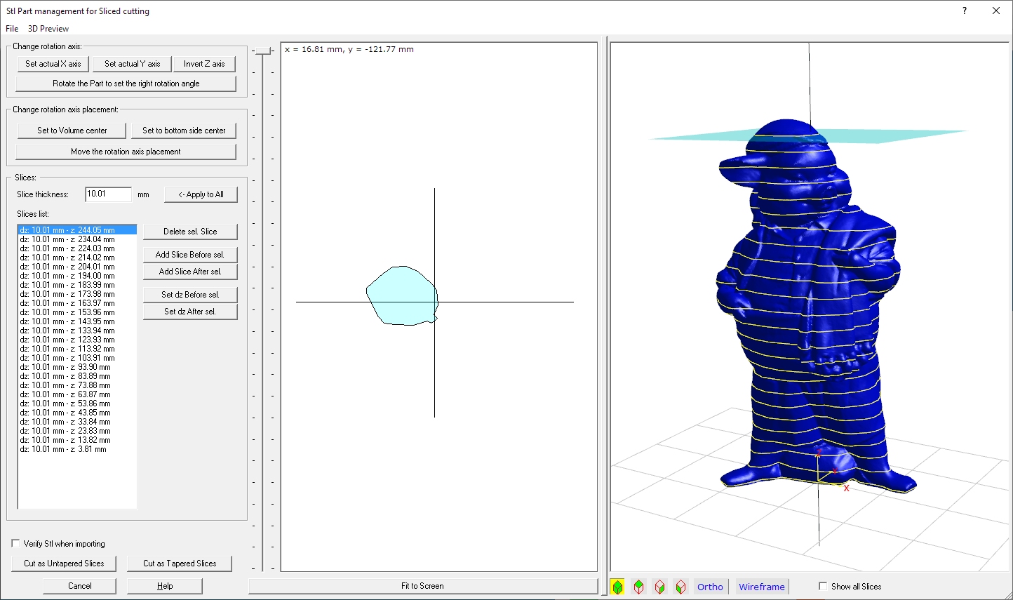
In the left side of the dialog you can see the controls to setup your Stl part.
In the middle a 2D preview, showing the computed projected section for the
rotation selected by the horizontal cursor.
In the right side the 3D preview of the Stl part.
Now we will explain in deep every single part of the dialog.
Left side: the parameters and commands
Change rotation axis Frame:
When you import a new Stl file, the original Z axis
is used as the rotation axis.
You can here select a new rotation axis between X and Y, considering that the
applied rotation axis will be the Z axis, as shown in the 3D picture.
You can also select to invert the orientation of the Z axis, if you want a
Top/Down inverted cut.
If this is not enough, as you have a Part with a strange angle, press the 'Rotate
the Part to set the right rotation angle' button. You will see
in the screen this new window:
You can as first select the axis to use to perform the rotation, and the right
View will be displayed in the 3D picture.
Then just press on of the button surrounding the angle step to apply some
rotation. Every button will apply a 1 x angle step, 5 x angle step, 15 x
angle step.
You can also select to use the Orthogonal view this can help to have a better
control over the 3D picture.
Then just press OK to confirm the new settings, or Cancel to ignore them.
Change rotation axis placement Frame:
When you import a new Stl file, the Z will be centered on the
Volume Center of the part, considering its max/min X and Y coordinates.
If you need to make more adjustements, just press the 'Move the rotation
axis placement' button. You will see in the screen this new
window:
You can as first select the axis to use to perform the movement, and the right
View will be displayed in the 3D picture.
Then just press on of the button surrounding the distance step to apply
some rotation. Every button will apply a 1 x distance step, 5
x distance step, 15 x distance step.
You can also select to use the Orthogonal view this can help to have a better
control over the 3D picture.
Then just press OK to confirm the new settings, or Cancel to ignore them.
Slices:
You set here the number and thickness of the Slicing
sections.
The simplest way to go is just to set the thickness of your foam panel, and
click "Apply to all".
The right number of slices will be created automatically.
If you prefer to work with sliced Parts of different thickness, you can
select a slice in the list and press:
Verify Stl when importing: checking this option, when you import a STL file it will be verified. If the application finds some problem you will advised, so you have the possiblity to fix them. You can for example use DevStl Tools to fix them, see the Startup dialog to run it. Enabling this option will perform longer processing time during the import job.
Command Buttons:
Middle side: the 2D preview
In the 2D preview you will see the geometry of the sliced
element as a XY section.
You can navigate the section by selecting a different item in the Slices list,
or just moving the vertical cursor placed at the left side of the 2D preview.
Pressing the 'Fit to screen' button you will maximize the drawing to the 2D preview window size.
Right side: the 3D preview
You can see here the 3D Preview of the Stl part.
The transparent cyan horizontal plan is the plan generating the section showed
in the 3D Preview.
Yellow contours will show all the horizonatal sections.
The optional grid can be customized by the '3D Preview' menu.
You can make measurements on the 3D preview selecting the Orthogonal view and
some predefined Top-Side-Front view.
The menu
Using the supplied menu you can control all the advanced settings.
File menu:
3D Preview menu:
I suggest also to take a look at this page, to better understand some important concepts of devFoam: DevFoam FAQ and important concepts
