|
||||
|
Picture vectorization
|
||||
Picture vectorization
You have 3 different way to create a Part from a raster image (picture):
The simplest way, if your picture is clean enough
Click the Cutting funcion you need
of the Startup
dialog (green icons) and select the picture (Gif,
Jpeg, Bmp, Png, Tif, Tga, Pcx). If enabled you will see the
'AutoTrace elements' dialog if you select a raster file. Finally
you will se the cutting dialog
where you can create the right cutting path.
If the result is not good, enable (if currently disabled) the 'AutoTrace
elements' dialog by the Setting link of the
Startup dialog and try to adjust as first the Thresold value.
Read also well the
'AutoTrace elements' help page to have more info to the right way
to have success.
A second way, Import regions or polylines in the Cad
section
To try this way create a new Cad drawing,
then use the "File - Import... - Import Regions from many file types..."
or the "File - Import... - Import Polylines from many file
types..." menu.
If enabled you will see the
'AutoTrace elements' dialog if you select a raster file. Finally
you will se the Imported regions in your Cad drawing.
Read also this pages
Importing regions in a new Cad drawing and
Importing polylines in a new Cad drawing.
If the result is not good, enable (if currently disabled) the 'AutoTrace
elements' dialog by the Setting link of the
Startup dialog and try to adjust as first the Thresold value.
Read also well the
'AutoTrace elements' help page to have more info to the right way
to have success.
A Last chance, use a background image in the Cad section
You can set it as a background image in a new Cad document, then trace it. See
also
And what can do devFoam Pro for the same problem?
Here are the step to follow:
Set the background image
After you created a New Cad document (see
Cad feature of devFoam) use the 'Format - Background image -
Add background image' menu
You will be prompted to select the image and if/how you want calibrate it. See
also
Inserting a background raster image in the drawing.
We suggest to select Manual calibration. Calibration is the operation to size
the image to the wanted dimension. After pressing OK you will be prompted to
click two points whose distance is known, for example the Height of the
picture.
Here is a picture of an example of raster background:
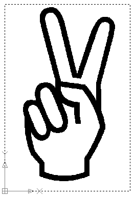
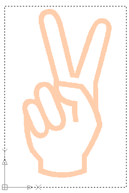
You can also use the menu 'Format - Background image - Set line
color of background image' to use a different color, so you
can see better the lines you'll go to trace:
Draw closed polylines around the contours
Now you must draw closed
Polylines around the contours. We suggest to use polylines so that
you haven't to fight against
dirty geometries.
You can use lines and arcs, and remember to use the Close command of the
command bar to close the polylines as the last step.
After you traced the polylines you can also select and refine them moving the
control points.
Here is a picture of the previous example with the polylines:
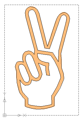
Select the closed polylines and go to cut
Now you can select the polylines and use the menu 'Cut - simple foam cutting of selected Parts' to start the Simple cutting dialog:
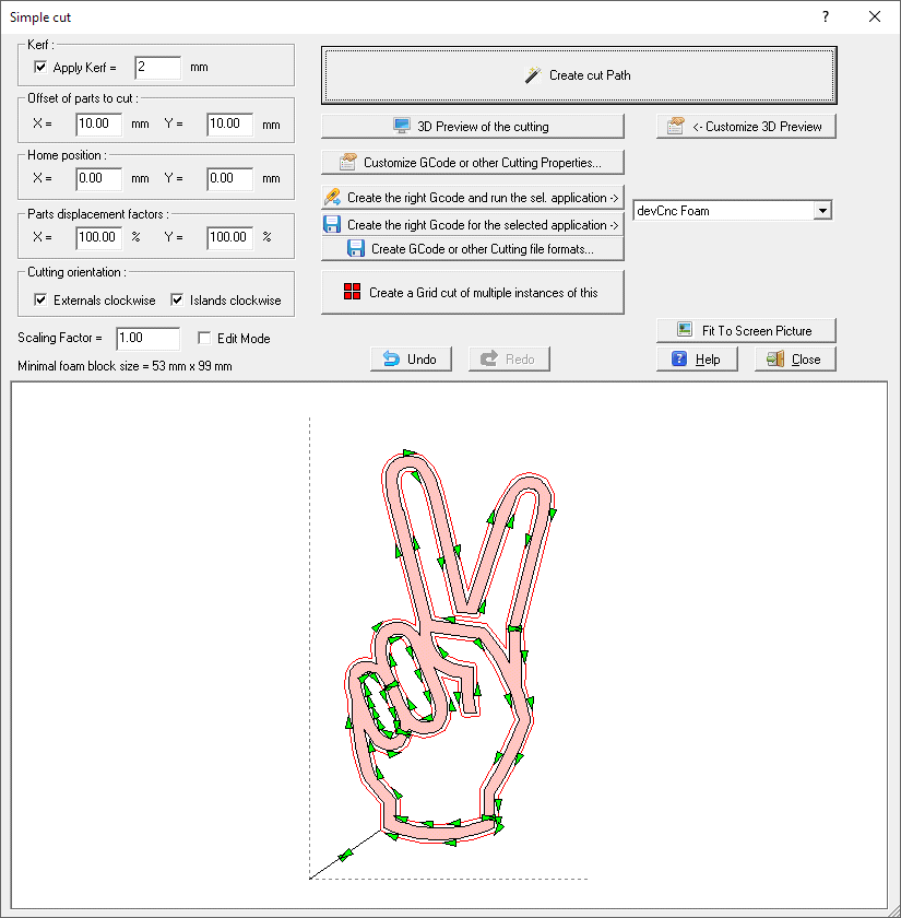
And you can as usually preview the cutting job in 3D:
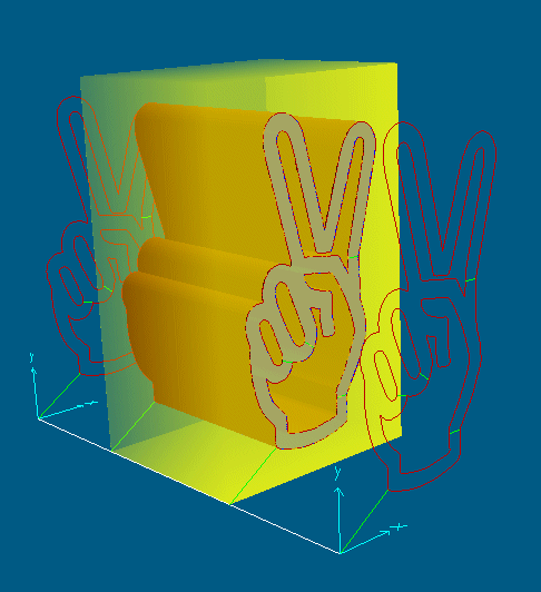
And what can do devFoam Pro for the same problem?