|
||||
|
CNC and dirty geometries
|
||||
CNC and dirty geometries
Sometime a shape appears good to the human eye, but it isn't accepted by a Cam application for your CNC machine.
For example let's take a look at this simple rectangle:
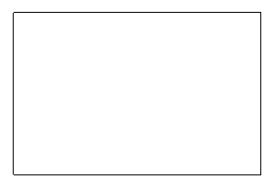
Looks like good, but probably it won't be accepted from a
Cam application.
If we take a look at the bottom left corner, zooming it, we can see this:
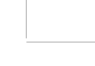
The corner is opened, because the vertices have slightly different
coordinates, they don't match each other!
This is one of the most common cause of dirty geometries.
The rules for a geometry to be a valid contour are:
You can see below an example of a contour with an autointersection, and so not clean:
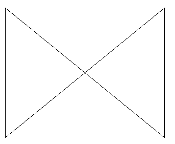
To make this geometry clean you must draw it as 2 triangles.
Clean geometries and Regions
To verify/validate the geometries to be clean DevFoam uses the Region object.
A Region is an element with
Here below an example of a Region with 2 islands:
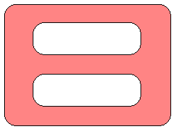
Region can always be cut as Parts. That' why we suggest to
work with Regions.
To create a Region you can use these commands:
See also this help page about Regions
Hot to create clean geometries
We suggest:
Hot to clean dirty geometries
If you already drew a dirty geometry, or if you imported it
from an external drawing (for example a DXF file), you can clean it.
You can adjust problems caused by unmatching vertices selecting the geometries
and moving the BLUE control points of the vertices.
See below:
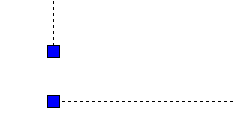
You can adjust intersection or autointersection problems by moving the vertices or breaking the geometries, see the FULLBREAK command.
A good piece of new: may be devFoam can help you in cleaning geometry
As the cleaning of dirty geometries is a rather annoying and
frustrating job, we developed a special feature to help you.
You can try to select the dirty geometries then use the 'Cut - Try
automatic Parts generation from selected elements' menu.
This function will try to:
Please note: Region and Parts are about the same thing. Tecnically a
Region is a Cad Object defined as help page about Regions.
A Part is a Region that you select and go to Cut. This because Part is the
usual term for an object to cut in Cam applications.
Here below an example of very dirty geometries:
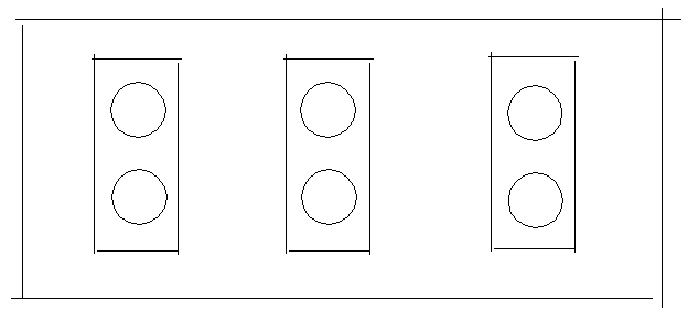
Applying the 'Cut - Try automatic Parts generation from selected elements' the result is:
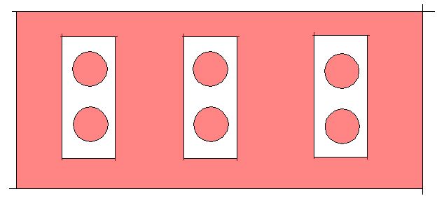
As you can see valid Regions are created as expected. Also Regions inside
Islands have been created.
The original dirty geometries are untouched, but the function creates new
Regions.
Enabling the menu 'Cut - Use automatic Parts generation for Cutting', when you select dirty geometries and go to cut them, they will be automatically converted (if possible) in Regions/Parts. You won't see them in the Cad documents, but only among the Parts to cut. See Simple cutting and Advanced cutting
I suggest also to take a look at this page, to better understand some
important concepts of devFoam:
DevFoam FAQ and important concepts