|
|
| Back to Wizard page. |
 |
|
|
|
TwistRot part
|
|
TwistRot part
You can get this dialog box pressing the 'Cut TwistRot
part' link located in the Startup dialog
You can use this if you own a
Cnc machine with an added rotary axis. If you press 'Cut
TwistRot Part' link
the following dialog will appear:
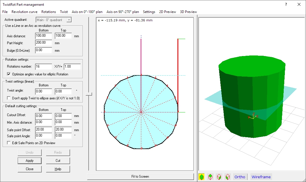
A TwistRot part is a solid generated by a Revolution curve
(in the upper dialog a simple segment) rotated on a Axis along a Rotation curve
(in the upper dialog a circle) with defined steps (also called Rotation number,
16 in the upper dialog).
The solid can also be twisted, this explains the TwistRot name.
The cut will performed alternating up and down cutting movements to rotations
of the foam block.
A lot of other settings can be applied to get very complex solids. This
TwistRot parts are more accurate and faster to cut than a 'Stl
Part', so, when possible, we suggest to use TwistRot part type.
Note: In this page we will refer to a section of the part cut
by an horizontal plan (see the transparent cyan plan in the 3D preview) as a
watermark section. You can also see the result as a cyan region in the 2D
preview.
In the left side of the dialog you can see the basic and most used parameters
and commands.
In the middle a 2D preview, showing the Revolution and Rotation curves.
In the right side the 3D preview.
All the advanced settings can be applied by the menu.
Now we will explain in deep every single part of the dialog.
Left side: the basic and most used parameters and
commands
Active
quadrant: if you select the Multiquadrant option this control will be enabled.
See the 'Revolution curve' menu. For simple parts just ignore it.
Use a Line or an Arc as revolution curve
Frame:
If you just need to use a simple Line or Arc as
revolution curve, you can just use this frame.
You can set the Bottom and Top distance of the Line or Arc from the rotation
axis, the Height of the part, and the Arc bugle. Using a Bulge = 0.0 you will
just get a Line.
If you want to use a more complex Revolution curve, see the 'Revolution curve'
menu.
Rotation settings Frame:
If you just need to use a circle or an
ellipse as Rotation curve, you can just use this frame.
You can set the Rotation number (how many cutting-rotation Jobs will be
performed) and the Ratio between the X and Y radius. Using 1.0 you will
just get a circle.
If you are using an ellipse, You can also let the application to optimise each
rotation angle to have the more accurate result. If not, all the rotations will
perform the same angle.
If you want to use a more complex Rotation curve, see the 'Rotation curve'
menu.
Twist settings (linear) Frame:
If you just need to use a linear Twist (or no
Twist at all), just refer to this dialog.
You can set an upper and lower Twist angle, then the cut will be performed
using a linear interpolation between this angles.
You can also decide if you want to apply the Twist also to the ellipse axes, if
you are using an ellipse. Nothing changes if you use a circle.
If you want to use a more complex Twist, see the 'Twist' menu.
Default cutting settings Frame:
Here you can apply important refinements to the cut:
-
The Cutout offset will remove the specified size from
the Bottom and Top sides. This size is measured along the vertical line (Z axes
of the 3D preview)
-
The Min axis distance lets you to specify a minimal
safe-uncut band from the rotation axis, for the Upper and Lower sides.
-
Safe points Offset and Angle: after every cutting, before
to apply the next rotation angle, the hot wire will move to these optional safe
points. Setting a 0.0 offset no movement will be applied to that side. Checking
the 'Edit Safe Points on 2D Preview' checkbox you can then see and drag 2
blue squares in the 2D preview to graphically set the Safe points.
Command Buttons:
Middle side: the 2D preview
I think the better thing is to explain what you can see here
by colour and line type. Consider also that you can turn on-off some components
by the '2D Preview' menu.
-
Red bold curve: this draws the real cutting line referred
to the Active quadrant (usually 0° quadrant).
-
Black dotted curve: this draws the theoretical cutting
curve. This can be modified for example by the Cutout offset. Often you cannot
see it as it just under the real Red bold curve...
-
Green lines: these draw the Paths to Safe points.
-
Purple line: the Twist curve. Usually vertical.
-
Brown line starting from the drawing origin (x=0.0,
y=0.0): the rotation axis on 90°-270° plans. Usually vertical.
-
Orange line starting from the drawing origin (x=0.0,
y=0.0): the rotation axis on 0°-180° plans. Usually vertical and often under
the Purple line.
-
Black dotted closed curve: this show the max size rotation
curve.
-
Cyan dotted horizontal line: this is a watermark line. You
can move it dragging the vertical slider at the left side of the 2D preview. A
transparent cyan plan will be rendered at that height in the 3D preview.
-
Cyan region with black bold contour: this shows the section
of the TwistRot part as cut by the watermark plan.The real cutting segment are
reported here. You can also see in Red dotted the normals toe each rotation
cut, and the rotation number.
-
Light yellow zones with no contour: the Regions drawing the
applied Min axis distances.
-
Light pink zones with no contour: the Regions drawing
the cutout offsets.
Pressing the 'Fit to screen' button you will maximize the
drawing to the 2D preview window size.
Right side: the 3D preview
You can see here the 3D Preview of the TwistRot part.
Consider also that you can turn on-off some components by the '3D Preview'
menu.
The transparent cyan plan can be moved by the vertical slider placed at the
left side of the 2D preview.
The optional grid can be customized by the '3D Preview' menu.
You can make measurements on the 3D preview selecting the Orthogonal view and
some predefined Top-Side-Front view.
The menu
Using the supplied menu you can control all the advanced
settings.
File menu:
-
Open...: Open an existent TwistRot part
-
Save: Save the actual TwistRot part
-
Save as...: Save the actual TwistRot part with a new file
name
-
Export as Stl file: Export the actual TwistRot part as a STL
file
Revolution curve menu:
The Revolution curve is the curve generating the lateral sides of the final
part, applying a Rotation according the specified Rotation curve.
For example applying a circle as a Rotation curve and a vertical segment
as a Revolution curve, you get the shape in the picture. A cylinder if you
apply a large number of Rotation steps.
-
Apply Line/Arc (see the "Use a Line or an Arc as revolution curve" frame):
You can reset to a simple Line/Arc after you loaded an external curve. Then you
will set the Line/Arc parameters using the controls included in the specified
frame
-
Load a custom Polyline from file: you can load an opened
Revolution curve for the selected quadrant from a vectorial or raster
file. When possible use a vectorial file, you can for example create this file
using the 'Draw and Cut not Tapered
parts'
link of the Startup dialog.
-
Create a Polygonal curve: you can create on the fly a
regular Polygonal curve for the selected quadrant . You will be prompted
for the required parameters.
-
Draw/Modify the custom Polyline: a Cad drawing app will
appear, with the actual Revolution curve of the selected quadrant
loaded. Draw the element, then just close this window. Saving the file is not
required, but optional. You can use undo if you don't like to keep the modified
drawing.
-
Sum new Polyline(s) to the actual one: the dialog
Sum new Polyline(s) to the actual one
will start. See the dialog Help file for more info.
-
Multiquadrant...: the Multiquadrant mode lets you to specify
till to 4 different Revolution curves, one for each quadrant at 0°, 90°, 180°
and 270°. The curve applied at intermediate rotations will be automatically
generated by interpoling (morphing) according to the shape of the surrounding
curves. You can then set the active quadrant using the Combo box included in
the left/top side of the dialog. All the operations on the Revolution curve
will be applied to the curve of the selected quadrant.
You can also select to have some symmetry, and to force the width of
the Quadrants to be controlled by the Rotation curve.
-
Scale the height of the custom Polyline to the value specified in the
dialog: you can select if you want to use the real Height of
the loaded Revolution curve, or the value specified in the dialog as Part
Height. In the latest case the Revolution curve will be scaled by the right
rate.
-
Minimal internal distance from Axis...: lets you to
specify a minimal safe-uncut band from the rotation axis, for the central side
along the Height. You can see the values for the Upper and Lower sides in
the dialog.
-
Fix bad concavities: you can select to fix bad
concavities. Bad concavities occur when the revolution curve come back along
the height. This will cause typically a bad cut. If this function in enabled
the application will try to fix simple cases. But the best way to go is always
to fix by hand the curve to a right path.
-
When applied 'Fix bad concavities' cut Upper/Lower bulges:
using this feature you can force the application to cut away upper and lower
vertical bulges. But the best way to go is always to fix by hand the curve to a
right path.
-
Max Watermark step length (the lower, the higher precision):
set the step length for generating watermark section. Probably the default
value will be ok for you. You can decrease this value to get a more accurate
part generation.
-
Flip Vertically: you can flip vertically the Revolution
curve of the selected quadrant.
-
Flip Horizontally: you can flip horizontally the
Revolution curve of the selected quadrant.
-
Attach to Axis Upper point: you move the Revolution
curve of the selected quadrant so that the Upper point will touch the rotation
axis.
-
Attach to Axis Lower point: you move the Revolution
curve of the selected quadrant so that the Lower point will touch the rotation
axis.
-
Move from Axis...: you move the Revolution curve of
the selected quadrant of the specified value.
-
Scale...: you Scale the Revolution curve of the
selected quadrant of the specified value.
-
Scale only Width...: you Scale the Width the
Revolution curve of the selected quadrant of the specified value
-
Scale only Height...: you Scale the Height
Revolution curve of the selected quadrant of the specified value
-
Apply Horizontal Slant angle...: you apply a
Horizontal Slant Angle of the specified value to the Revolution curve
of the selected quadrant
-
Apply Vertical Slant angle...: you apply a Vertical
Slant Angle of the specified value to the Revolution curve of the
selected quadrant
-
Smooth: you Smooth the Revolution curve of the selected
quadrant, using internally a special Spline
-
Fillet...: you apply a Fillet operation of the
specified value to the sharp angles of the Revolution curve of the
selected quadrant
-
Chamfer...: you apply a Chamfer
operation of the specified value to the sharp angles of the
Revolution curve of the selected quadrant
-
Create Facets...: you can modify the Revolution curve of
the selected quadrant creating a specified number of Facets
Rotation curve menu:
A Rotation curve describe the rotation applied to the
Revolution curve, to build the lateral sides of the final part.
For example applying a circle as a Rotation curve and a vertical segment
as a Revolution curve, you get the shape in the picture. A cylinder if you
apply a large number of Rotation steps.
-
Apply simple Rotation (see the Rotation settings frame):
You can reset to a simple Circle/Ellipse after you loaded an external
curve. Then you will set the Circle/Ellipse parameters using the controls
included in the specified frame
-
Load a custom closed Polyline from file: you can load a
closed Rotation curve from a vectorial or raster file. When possible
use a vectorial file, you can for example create this file using the
'Draw and Cut not Tapered parts'
link of the Startup dialog.
-
Create a Polygonal closed curve: you can create on the fly
a regular closed Polygonal curve. You will be prompted for the required
parameters.
-
Draw/Modify the custom closed Polyline: a Cad drawing app
will appear, with the actual Rotation curve loaded. Draw the element, then
just close this window. Saving the file is not required, but optional. You can
use undo if you don't like to keep the modified drawing.
-
Load a custom Polyline from file for the 0°-90° quadrant: you
can load an opened Rotation curve from a vectorial or raster
file. In this case the drawn Rotation curve must just specify the path in the
0°-90°, then the full Rotation curve will be build by the application using
symmetry rules. When possible use a vectorial file, you can for example create
this file using the 'Draw and Cut not
Tapered parts'
link of the Startup dialog.
-
Draw/Modify the custom Polyline for the 0°-90° quadrant: a
Cad drawing app will appear, with the actual Rotation curve of the 0°-90°
quadrant. In this case the drawn Rotation curve must just specify the path in
the 0°-90°, then the full Rotation curve will be build by the application using
symmetry rules. Draw the element, then just close this window. Saving the file
is not required, but optional. You can use undo if you don't like to keep the
modified drawing.
-
Apply the real size of the Rotation custom polyline: you
can select if you want to use the real size of the loaded Rotation curve,
or the value specified by the Revolution curve. In the latest case the Rotation
curve will be scaled by the right rate.
-
Optimise the number of real cuts for not Circular rotations:
You can create the minimum set of Rotations according to the Tolerance
specified in the below command.
-
Tolerance used to optimise the number of real cuts: the
tolerance used to compute the minimum set of Rotations, see the above command
-
Max. number of optimised real cuts: You can limit here the
number of Rotations created by the above commands
-
Flip Vertically: you can flip vertically the Rotation
curve.
-
Flip Horizontally: you can flip horizontally the Rotation
curve.
-
Scale...: you Scale the Rotation curve of
the specified value.
-
Scale only Width...: you Scale the Width the
Rotation curve of the specified value.
-
Scale only Height...: you Scale
the Height the Rotation curve of the specified value.
-
Rotate...: you Rotate the Rotation curve of
the specified angle.
-
Smooth: you Smooth the Rotation curve, using
internally a special Spline
-
Fillet...: you apply a Fillet operation of the
specified value to the sharp angles of the Rotation curve.
-
Chamfer...: you apply a Chamfer
operation of the specified value to the sharp angles of the
Rotation curve
-
Create Facets...: you can modify the Rotation
curve creating a specified number of Facets
Twist menu:
A Twist curve describe the optional Twist applied to each watermark section,
according to its height. The most common curve is a segment (simple case) and
that describes a linear Twist from the top and bottom Twist values.
-
Apply simple Twist (see the Twist settings frame): You can
reset to a simple linear Twist after you loaded an external curve.
Then you will set the Twist top and bottom values using the controls
included in the specified frame
-
Load a custom Polyline from file: you can load an
opened Twist curve from a vectorial or raster file. When possible use a
vectorial file, you can for example create this file using the
'Draw and Cut not Tapered parts'
link of the Startup dialog.
-
Draw/Modify the custom Polyline: a Cad drawing app will
appear, with the actual Twist curve loaded. Draw the element, then
just close this window. Saving the file is not required, but optional. You can
use undo if you don't like to keep the modified drawing.
-
Sum new Polyline(s) to the actual one: the dialog
Sum new Polyline(s) to the actual one
will start. See the dialog Help file for more info.
-
Apply the defined Twist to the full Height (ignore Upper/Lower cutouts):
you can define the way the Twist curve will be applied, when you have
Upper/Lower cutouts.
-
Flip Vertically: you can flip vertically the Twist
curve.
-
Flip Horizontally: you can flip horizontally
the Twist curve.
-
Move...: you can move horizontally the Twist
curve along the X coordinate.
-
Scale Width...: you Scale the
Width the Twist curve of the specified value.
-
Apply Vertical Slant angle...: you can apply a Slant angle
to the Twist curve. If you apply it two or more times, the new will be summed
to the previous one and won't replace it!
-
Smooth: you Smooth the Twist curve, using internally
a special Spline
-
Fillet...: you apply a Fillet operation of the
specified value to the sharp angles of the Twist curve.
-
Chamfer...: you apply a Chamfer
operation of the specified value to the sharp angles of
the Twist curve
-
Create Facets...: you can modify the Twist
curve creating a specified number of Facets
Axis on 0°-180° plan menu:
You can apply more control to the final part modifying
the shape of this axis. This axis define the center of the local Rotation curve
applied to generate each watermark section. The full Axis can be modified
in its views on the different 0°-180° and 90°-270° plans
-
Vertical: You can reset to a
simple vertical Axis after you loaded an external curve or
modified it
-
Load a custom Polyline from file: you can load an
opened Axis curve from a vectorial or raster file. When possible use a
vectorial file, you can for example create this file using the
'Draw and Cut not Tapered parts'
link of the Startup dialog.
-
Draw/Modify the custom Polyline: a Cad drawing app will
appear, with the actual Axis curve loaded. Draw the element, then
just close this window. Saving the file is not required, but optional. You can
use undo if you don't like to keep the modified drawing.
-
Sum new Polyline(s) to the actual one: the dialog
Sum new Polyline(s) to the actual one
will start. See the dialog Help file for more info.
-
Apply to the full Height (ignore Upper/Lower cutouts): you
can define the way the Axis curve will be applied, when you have
Upper/Lower cutouts.
-
Flip Vertically: you can flip vertically the Axis
curve.
-
Flip Horizontally: you can flip horizontally the Axis
curve.
-
Move...: you can move horizontally the Axis
curve along the X coordinate.
-
Scale Width...: you Scale the
Width the Axis curve of the specified value.
-
Apply Vertical Slant angle...: you can apply a Slant angle
to the Axis curve. If you apply it two or more times, the new will be
summed to the previous one and won't replace it!
-
Smooth: you Smooth the Axis curve, using internally a
special Spline
-
Fillet...: you apply a Fillet operation of the
specified value to the sharp angles of the Axis curve.
-
Chamfer...: you apply a Chamfer
operation of the specified value to the sharp angles of
the Axis curve
-
Create Facets...: you can modify the Axis
curve creating a specified number of Facets
Axis on 90°-270° plan
menu:
You can refer to the 0°-180° plan menu explanation, see
above
Settings menu:
-
Fix concavities on XY plans (watermark sections):
in some conditions the watermark sections can perform concavities. This will
cause usually bad cuts, the application can try to remove the concavities for
you.
2D Preview menu:
-
Show Cut out zones: show/hide the cut out zones, rendered
as light pink regions
-
Show Min Axis zones: show/hide the Min axis distance
zones, rendered as light yellow regions
-
Show Bad convexity points: show/hide a little blue circle
where a convexity of the Revolution curve starts
-
Show Warning: show/hide warning messages about
problems in the part generation
-
Show Watermark section (see vertical cursor): show/hide
the cyan watermark section
-
Advanced: Show real cutting points and angles on Watermark section:
show/hide more details about the cut in the cyan watermark section
-
Show Twist Curve: show/hide the purple Twist curve
-
Show Axis on 0°-180° plan Curve: show/hide
this orange Axis curve
-
Show Axis on 90°-270° plan Curve: show/hide this
brown Axis curve
3D Preview menu:
-
Select Part colour: you can change the part colour
-
Grid settings and Background colour: you can change the
background colour and grid settings
-
Show Watermark plan: show/hide the cyan watermark plan
-
Show Warning: show/hide warning messages about
problems in the part generation
-
Apply Smoothing: Apply smoothing to the part surface. The
process time can be slower when enabled.
I suggest also to take a look at this page, to better understand some
important concepts of devFoam:
DevFoam FAQ and important concepts