|
|
| Back to start page. |
 |
|
|
|
Grid cut
|
|
Grid cut
You can get this dialog box pressing the 'Create a Grid
cut of multiple instances of this' located in the Simple
cutting and
Cut Nested Parts dialogs
Here you can create a grid od cell, where
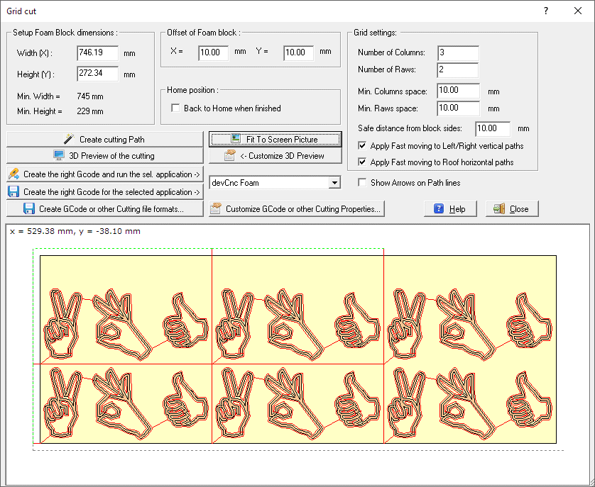
every cell includes the original parts and cutting paths. The following
dialog will appear:

The first thing to do
is to set the Foam block dimension, see the 'Setup Foam block dimensions'
frame.
You can read there also the minimal dimension required, calculated using the
selected parts dimensions and adding the Min. space between the Parts.
Offset of parts to cut frame -
you specify how far from the 0, 0 origin the bottom/left corner
of theFoam Block will be placed
Back to Home when finished - You can
also force the hot wire to come back following a safe path to the original
side, when the cutting job is finished.
Grid settings
You must specify here:
-
The number of Columns and Rows of the Grid
-
The space between Columns and Rows
-
Safe distance from block sides: value.
The safe distance from the Foam block sides applied for out of Foam fast
movements
-
Apply Fast moving to Left/Right vertical paths
- if enabled the Left/Right vertical movements out of the specified block will
be performed af Fast speed
-
Apply Fast moving to Roof horizontal paths-
if enabled the Roof horizontal movements out of the specified block
will be performed af Fast speed
In the bottom part you can see some buttons, to create,
customize and export the cutting Path:
-
Create cut Path - this is the main
button, as creating the
Cutting path is the first operation to do. Click the button and
the
Cutting path will created automatically. You can then modify the
entry/exit points by enabling the
Edit mode checkbox and
dragging the blue control points
-
-
Customize GCode or other Cutting Properties...
- clicking this button you can see a popup menu wher you can:
-
We are making partnership with Companies supplying
good controllers and the related Gcode interpreter for Foam cutting.
You can select one the approved controller/applications then:
-
Press the 'Run the selected
app. ->' button to create a special GCode file customized
for the selected controller/application and run the application with the right
file already loaded
-
Press the 'Create the right
Gcode for ->' button to create a special GCode file
customized for the selected controller/application
-
Create GCode or other Cutting file formats...- clicking
this button you can see a popup menu wher you can:
-
Export Path to 2 Axis Gcode - if you are
driving your foam cutting machine as a simple 2 axis, this is the button to
create the GCode. You can customize the GCode using the
Customize 2 Axis Gcode button
-
Export Path to 4 Axis Gcode - if you are
driving your foam cutting machine as a 4 axis, this is the button to create the
GCode. You can customize the GCode using the
Customize 4 Axis Gcode button
-
Export Path to DXF - DXF files are a
standard in Cad applications. You can customize the DXF using the
Customize DXF button
-
Export Path to DAT - DAT files are used
to describe a single polyline, some CNC driving software likes to import them
-
Export Path to Hpgl/Plt - Hpgl/Plt files
are used to describe the plotting of a drawing, some CNC driving softare likes
to import them. Only simple command like SP, PU, PD are used here.
-
Export Path to GMFC script .CUT file - if
you use GMFC to drive your CNC, you can create a .CUT file and import it in
GMFC as a Script file. When you click this button you will be prompted for some
parameters in the
GMFC
.cut file creation dialog
-
Fit to screen picture - you can maximize
the content of the picture
I suggest also to take a look at
this page, to better understand some important concepts of devFoam:
DevFoam FAQ and important concepts
