|
||||
|
Tapered Parts Cutting wizard: Foam block placement and setting
|
||||
Tapered Parts Cutting wizard: Foam block placement and setting Pro version only
This wizard includes 5 pages:
The following dialog will appear:

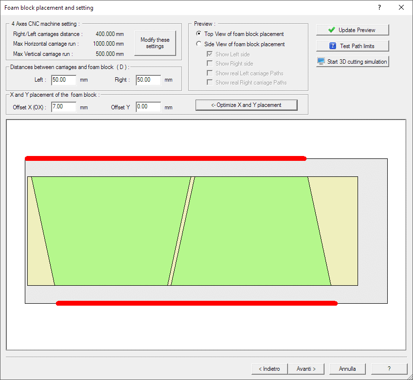
In this panel you will define the placement of the material block over the cutting table.
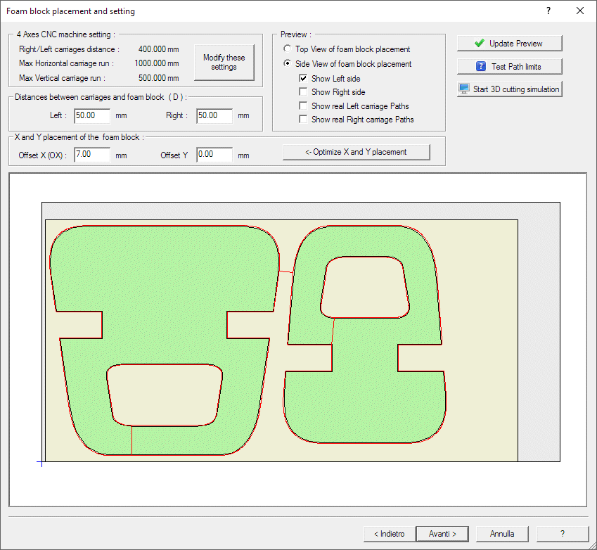
Two main views are available, to check the right placement of the material block:
How to proceed:
As first check if the dimensions of your CNC machine are right, or set the right size by the Modify these settings button.
You can now use the 'Test Path limits' button to see if the default placement setting is good enough. If not make a step by step check:
Check if the Horizontal Bold Red lines in the Top View picture are all inside the max X travel. The Horizontal Bold red lines in the Top View picture show the real X run of the left and rigth carriages. The light gray rectangle shows the top view of the cutting table. See the picture above.
Check also if the Y run of both the carriages are inside the max Y travel of the carriages. See the Side View picture, enabling the real left and right carriage path. Moving left or right the material block can correct these values, depending on the tapered geometry of the Tapered Parts. As a rule of thumb, move the material block near the carriage where the Paths are wider, then press 'Update Preview' to update the picture. See the below picture:
Press now the 'Optmize X and Y placement' to compute the right offset.
The X offset is the distance of the nearest face of the material from the CNC
origin, along the horizontal X axe.
The Y offset is the height of the bottom face of the
material over the CNC origin (cutting table), along the vertical Y
axe.
If the bock you are going to cut is rather small, probably all this adjustement is not required and the supplied initial parameters will be good enough to continue

Press now the 'Optmize X and Y placment' to compute the right offset.
If the block you are going to cut is rather small, probably all this adjustement is not required and the supplied initial parameters will be good enough to continue.
You can also check that using the 'Test Path limits' button
Press the 'Start 3D cutting simulation' button to run the devSim Cnc Foam application that show a 3D simulation of the cutting Job.
More info about the picture in this dialog: